Nutanix Resiliency – Part 8 – Node failure rebuild performance with RF3 & Erasure Coding (EC-X)

As discussed in Part 1 for RF2 and Part 3 for RF3, a critical factor when discussing the resiliency of ADSF is the speed at which compliance with the configured Resiliency Factor can be restored in the event of a drive or node failure.

Let’s do a a quick recap of Part 1 and 3 and then look an an example of the performance of ADSF for a node failure when RF3 with Erasure Coding (EC-X) is used.

Because the rebuild operation (regardless of the configured resiliency factor or data reduction such as EC-X) is a fully distributed operation across all nodes and drives (i.e.: A Many to many operation), it’s both very fast and the workload per node is minimised to avoid bottlenecks and to reduce the impact to running workload.

Remember, the rebuild performance depends on many factors including the size of the cluster, the number/type of drives (e.g.: NVMe, SATA-SSD, DAS-SATA) as well as the CPU generation and network connectivity, but with this in mind I thought I would give an example with the following hardware.

The test bed is a 15 node cluster with a mix of almost 5 year old hardware including NX-6050 and NX-3050 nodes using Ivy Bridge 2560 Processors (Launched Q3, 2013), each with 6 x SATA-SSDs ranging in size and 2 x 10GB network connectivity.

Note: As Erasure Coding requires more computational overhead than RF2 or 3, faster processors would make a significant difference to the rebuild rate as they are used to calculate the parity whereas Resiliency Factor simply copies replicas (i.e.: No parity calculation required).

For this test, the cluster was configured with RF3 and Erasure Coding.


As with previous tests, the node failure is simulated by using the IPMI interface and using the “Power off server – immediate” option as shown below. This is the equivalent of pulling the power out of the back of a physical server.

IPMIPowerOff


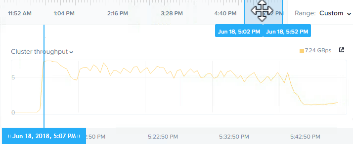
Below is a screenshot from the Analysis tab in Nutanix HTML 5 PRISM GUI. It shows the storage pool throughput during the rebuild from the simulated node failure.

RF3ECXRebuildThroughput

As we can see, the chart shows the rebuild shows a peak of 7.24GBps and sustains over 5GBps throughput until completion. The task itself took just 47mins as shown below from the Chronos Master page which can be found at http://CVM_IP:2011.

NodeFailureTaskDuration

So in this example, we see that even with Erasure Coding (EC-X) enabled, Nutanix ADSF is able to rebuild at an extremely fast pace all while providing great capacity savings over RF3.

Summary:

  • Nutanix RF3 with or without Erasure Coding is vastly more resilient than RAID6 (or N+2) style architectures
  • ADSF performs continual disk scrubbing to detect and resolve underlying issues before they can cause data integrity issues
  • Rebuilds from drive or node failures are an efficient distributed operation using all drives and nodes in a cluster regardless of Resiliency Factor or data reduction configuration.
  • A recovery from a node failure (in this case, the equivalent of 6 concurrent SSD failures) with Erasure Coding can sustain over 5GBps even on 5yo hardware.

Index:
Part 1 – Node failure rebuild performance
Part 2 – Converting from RF2 to RF3
Part 3 – Node failure rebuild performance with RF3
Part 4 – Converting RF3 to Erasure Coding (EC-X)
Part 5 – Read I/O during CVM maintenance or failures
Part 6 – Write I/O during CVM maintenance or failures
Part 7 – Read & Write I/O during Hypervisor upgrades
Part 8 – Node failure rebuild performance with RF3 & Erasure Coding (EC-X)
Part 9 – Self healing
Part 10: Nutanix Resiliency – Part 10 – Disk Scrubbing / Checksums

Nutanix Resiliency – Part 6 – Write I/O during CVM maintenance or failures

In Part 5 we covered how Read I/O is serviced during CVM maintenance or failure so now we need to cover the arguably more difficult and critical task of servicing write I/O during the same maintenance or failure scenarios.

For those of you who read Part 5, this next section will look familiar. For those who have not read Part 5 I would ask that you please do so but let’s quickly cover off again the basics of how Nutanix ADSF writes and protects data.

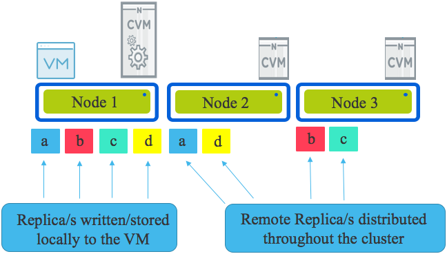
Looking an the following diagram we see a three node cluster with a single Virtual Machine. The VM has written some data represented by a,b,c & d & under normal circumstances all writes will have one replica written to the host running the VM (in this case Node 1) and the other replica (or replicas in the case of RF3) are distributed throughput the cluster based on disk fitness values. The disk fitness values (or what I call “Intelligent replica placement”) ensure data is placed in the most optimal place the first time based on capacity and performance.

RF2Overview

If one or more nodes are added to the cluster, the Intelligent replica placement will send proportionally more replicas to those nodes until the cluster is in a balanced state. In the very unlikely even no new writes are occurring, ADSF has a background disk balancing process which will balance the cluster as a low priority.

Now that we know the basics of how Nutanix protects data using multiple replicas (called “Resiliency Factor”) let’s talk about what happens during a Nutanix ADSF storage layer upgrade.

Upgrades are initiated by a one-click process and performed in rolling style one controller VM (CVM) at a time regardless of the configured Resiliency Factor and if Erasure Coding (EC-X) is used or not. The rolling upgrade put simply takes one CVM offline at a time, performs the upgrade, performs and self check and then rejoins the cluster and then repeats the process on the next CVM.

One of the many advantages of Nutanix decoupling the storage from the hypervisor (i.e.: not embedding storage into the kernel) is that upgrades and even storage layer failures do not impact the running Virtual machines.

VMs do not need to be restarted (i.e.: Like a HA event) nor do they need to migrate (e.g.: vMotion) to another node. VMs continue without interruption to storage traffic even when the local controller is offline for any reason.

If the local CVM is down for maintenance or due to failure, the write I/O is dynamically re-directed throughout the cluster.

Let’s look at a Write I/O when the CVM local to a VM is offline (for any reason).

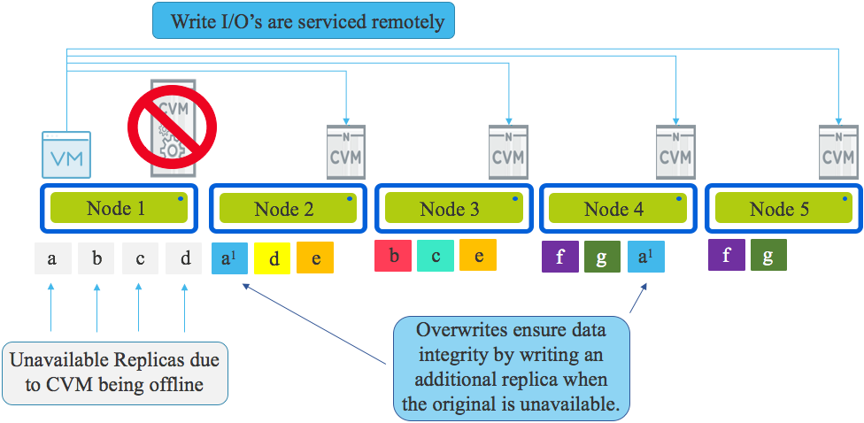
The local CVM being offline means the physical drives (NVMe, SSD, HDD etc) are not available meaning the local data (replicas) is unavailable.

All write I/O will be continue to function and remain in compliance with the configured Resiliency Factor (RF), however rather than one replica being written locally, it will be written to a remote CVM over the network as will the other replica/s.

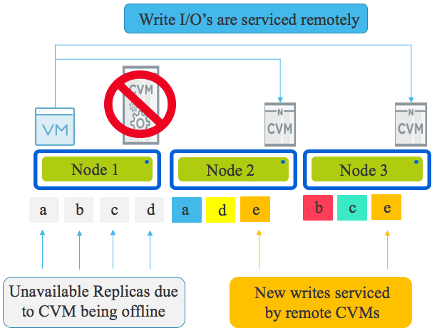
In the example below, we have a three node cluster so the VM on Node 1 is writing both replicas for “E” over the network to Node 2 and 3. This is how new data is serviced.

NewWriteIO

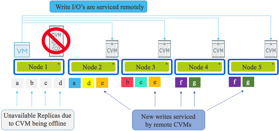
If more nodes existed in the cluster, the write traffic would be distributed evenly using Intelligent Replica Placement across all nodes within the cluster as shown below.

WriteIOLocalCVMDown5Nodes

In the event data is being overwritten (as opposed to net new data) and the local replica is unavailable due to the CVM being offline, Nutanix ensures data integrity is maintained by overwriting the available replica and writing a second (or third for RF3) copy on another node in the cluster.

OverwriteWhenLocalCVMisDown

This is critical because if data is not always kept in compliance with it’s resiliency factor (FTT for VMware vSAN) a subsequent drive or node failure would cause data loss.

A major resiliency advantage Nutanix has over vSAN is the fact we always remain in compliance with the configured Resiliency Factor including during all failure and maintenance scenarios. vSAN however does not maintain it’s configured FTT level during all host maintenance and failure scenarios. For VMs on vSAN configured with FTT=1, in the event the host hosting one vSAN disk “object” is offline for maintenance, new overwrites are not protected so a single drive failure can result in data loss.

Chief Technologist at VMware, Duncan Epping recently posted an article titled: “VSAN 6.2 : Why going forward FTT=2 should be your new default”  where he recommended FTT=2 as the new default for vSAN customers.

I have to agree with Duncan, but I wouldn’t say vSAN should be set to FTT=2, I would say it MUST be set to FTT=2 as FTT=1 creates a single point of failure for over-writes during maintenance or failures and this is unacceptable for most production workloads with VDI being one of a potential few exceptions in some cases.

Nutanix on the other hand does not have the same architectural flaw as vSAN and as such, RF2 is extremely resilient and suitable for even the most critical environments as explained in this series.

That and the fact ADSF is able to restore resiliency in such a timely manner, RF2 has far superior resiliency compared to vSAN FTT=1.

In the next part we will cover the critically important topic of how VMs are impacted during hypervisor (ESXi, Hyper-V, XenServer and AHV) upgrades.

Summary:

  1. Write I/O continues uninterrupted if the local CVM is offline
  2. Write I/O is distributed throughout the cluster evenly thanks to Intelligent Replica Placement
  3. All new data is written in compliance with the configured Resiliency Factor
  4. Overwrites of existing data is always written in compliance with the configured Resiliency Factor by writing a new replica where the original replica is not available.
  5. Data integrity is ALWAYS maintained regardless of a CVM being under maintenance or failure.
  6. Nutanix RF2 is more resilient than vSAN FTT=1 despite each claiming to maintain two copies of data.

Index:
Part 1 – Node failure rebuild performance
Part 2 – Converting from RF2 to RF3
Part 3 – Node failure rebuild performance with RF3
Part 4 – Converting RF3 to Erasure Coding (EC-X)
Part 5 – Read I/O during CVM maintenance or failures
Part 6 – Write I/O during CVM maintenance or failures
Part 7 – Read & Write I/O during Hypervisor upgrades
Part 8 – Node failure rebuild performance with RF3 & Erasure Coding (EC-X)
Part 9 – Self healing
Part 10: Nutanix Resiliency – Part 10 – Disk Scrubbing / Checksums

Nutanix AOS 5.5 delivers 1M read IOPS from a single VM, but what about 70/30 read/write?

I recently wrote Nutanix AOS 5.5 delivers 1M IOPS from a single VM, but what happens when you vMotion which showed the impact of a vMotion was around -10% for a period of approx. 3 seconds before read performance resumed back to pre-migration levels.

In this post I will be addressing the question about performance for a single VM with a more realistic 70% read, 30% write IO profile which was performed using an 8k IO size and what the impact is during and after a live migration.

While not surprising to Nutanix customers, this result shows a maximum starting baseline of 436K random read and 187k random write IOPS and immediately following the migration performance reduced to 359k read and 164k write IOPS before achieving greater performance than the original baseline @ 446k read and 192k IOPS within a few seconds.

So in comparison to 100% random read which achieved just over 1 million 8k IOPS, the 70/30 mix achieves in the ballpark of 600k IOPS which is very respectable. Not bad for a platform which Nutanix competitors continue to describe as only being good for VDI. Considering even the largest array from a leading all flash SAN vendor is only advertising performance in the hundreds of thousand random read range, it shows Nutanix unique hyper-converged architecture can achieve higher performance than a monolithic all flash array from a single VM.

This shows that with the unique Nutanix Acropolis Distributed Storage Fabric, very high performance at low latency can be achieved with real world IO patterns even during and after live migrating the virtual machine across a distributed platform.

This result is further evidence of the efficiency of Nutanix Acropolis Hypervisor, AHV (which is included at no additional charge with AOS) as well as the IO path running in user space (not the much hyped in-kernel). This is in part thanks to AHV Turbo Mode which optimised the IO path which was announced at .NEXT 2017 in Washington. In addition to these excellent levels of performance, they can be sustained even when using data protection features such as snapshots as shown in recent post I wrote about Nutanix X-ray tool where I used the Snapshot impact scenario to compare Nutanix AHV and a leading hypervisor and SDS product. If you don’t have time to read the post, in short, the Nutanix competitors performance degraded as snapshots were taken while Nutanix AHV’s performance remained consistent which is essential for real world scenarios, especially with business critical applications.

With Nutanix unique ability to scale out performance using storage only nodes, even higher performance can be achieved without modification to the virtual machine to applications which gives Nutanix further advantage over the competition.

Nutanix data locality ensures optimal performance by ensuring new data is always local to the VM and cold data can remain remote indefinitely while only hot data will be migrated locally if/when required at a 1MB granularity. This translates to intelligent data locality and not brute force locality as it is frequently mistaken to be.

Back to Part 1