How to successfully Virtualize MS Exchange – Part 7 – Storage Options

When virtualizing Exchange, we not only have to consider the Compute (CPU/RAM) and Network, but also the storage to provide both the capacity and IOPS required.

However before considering IOPS and capacity, we need to decide how we will provide storage for Exchange as storage can be presented to a Virtual Machine in many ways.

This post will cover the different ways storage can be presented to ESXi and used for Exchange while subsequent posts will cover in detail each of the options discussed.

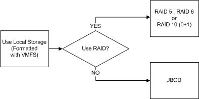
First lets discuss Local Storage.

What I mean by Local Storage is SSD/HDDs within a physical ESXi hosts that is not shared (e.g.: Not accessible by other hosts).

This is probably the most basic form of storage we can present to ESXi and apart from the Hypervisor layer could be considered similar to a physical Exchange deployment.

UseLocalStorage

Next lets discuss Raw Device Mappings.

Raw Device Mappings or “RDMs” are where shared storage from a SAN is presented through the hypervisor to the guest as a native SCSI device and enables.

RDMs

For more information about Raw Device Mappings, see: About Raw Device Mappings

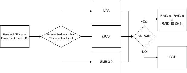
The next option is Presenting Storage direct to the Guest OS.

It is possible and sometime advantageous to presents SAN/NAS storage direct to the Guest OS via NFS , iSCSI or SMB 3.0 and bypasses the hyper-visor all together.

DirectInGuest

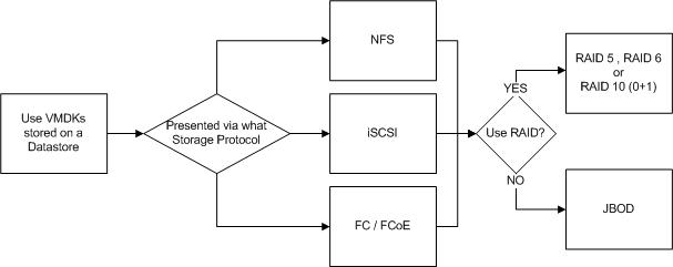
The final option we will discuss is “Datastores“.

Datastores are probably the most common way to present storage to ESXi. Datastores can be Block or File based, and presented via iSCSI , NFS or FCP (FC / FCoE) as of vSphere 5.5.

Datastores are basically just LUNs or NFS mounts. If the datastore is backed by a LUN, it will be formatted with Virtual Machine File System (VMFS) whereas NFS datastores are simply NFS 3 mounts with no formatting done by ESXi.

ViaDatastore

For more information about VMFS see: Virtual Machine File System Technical Overview.

What do all the above options have in common?

Local storage, RDMs, storage presented to the Guest OS directly and Datastores can all be protected by RAID or be JBOD deployments with no data protection at the storage layer.

Importantly, none of the four options on their own guarantee data protection or integrity, that is, prevent data loss or corruption. Protecting from data loss or corruption is a separate topic which I will cover in a non Exchange specific post.

So regardless of the way you present your storage to ESXi or the VM, how you ensure data protection and integrity needs to be considered.

In summary, there are four main ways (listed below) to present storage to ESXi which can be used for Exchange each with different considerations around Availability, Performance, Scalability, Cost , Complexity and support.

1. Local Storage (Part 8)
2. Raw Device Mappings  (Part 9)
3. Direct to the Guest OS (Part 10)
4. Datastores (Part 11)

In the next four parts, each of these storage options for MS Exchange will be discussed in detail.

Back to the Index of How to successfully Virtualize MS Exchange.

Competition Example Architectural Decision Entry 2 – Use of RDMs in Standard IaaS Clusters

Name: Chris Jones
Title: Virtualization Architect
Twitter: @cpjones44
Profile: VCP5 / VCAP5-DCD

Problem Statement

VMs require more than 1.9TB in a single disk. The existing virtual environment has LUNs provisioned that are 2TB in size. As these VMs have virtual data disks (VMDKs) that are > 1.9TB in size, alarms are being triggered by the infrastructure monitoring solution and raising Incident tickets to the Virtual Infrastructure support queue.

Assumptions

1. Data within the OSI must reside within the VM and not on some kind of IP based store (like a NAS share).

2. vSphere datastores are presented through FC and not IP based stores (ie. NFS).

3. vSphere Hypervisor is ESXi 4.1.

4. There is no requirement for the VMs to be performing SAN specific functionality or running SCSI target-based software.

Constraints

1. The implemented monitoring solution cannot be customised with triggers and monitoring policies for individual objects within the environment (ie. having one monitoring policy per individual or sub-group of datastores).

2. Maximum vSphere datastore size in version 4.1 is 2TB minus 512 bytes.

3. Unable to upgrade beyond ESXi 4.1 Update 3.

Motivation

1. Reduce the number of incident tickets being raised, thus improving SLA posture.

2. Reduce the requirement to span single Windows logical volumes across multiple VMDKs.

Architectural Decision

Turn the disk into an RDM (Virtual Compatibility Mode) to remove the level of monitoring from the vSphere layer.

Alternatives

1. Create smaller VMDKs (ie. 1-1.5TB disks) and create a RAID0 volume within the guest OS.

2. Change the level of alerting so that tickets are not raised for alerts that trigger beyond 90%.

3. Turn the disk into an RDM to remove the level of monitoring from the vSphere layer.

4. Thin Provision the virtual disks

5. Store the data within the guest on some kind of IP based storage (NAS/iSCSI target).

Justification

1. Option 5 goes against the assumption that data must be local to the VM, so was ruled out.

2. Whilst thin provisioning (Option 4) is an attractive solution, this option is ruled out based on a wider infrastructure decision to thick provision all disks in the environment to reduce the risk to datastores filling up and critical business VMs stopping.

3. Option 1 via smaller VMDKs spread across multiple vSphere datastores will result in these alerts disappearing, however it will create issues when trying to execute a DR recovery for either the individual disks (Active/Passive) or the whole VM (Active/Cold). All that’s needed is for one VMDK not to be replicated and the whole Windows volume will be corrupted, or for the VMDKs to be mounted in the wrong order. Multiple VMDKs to one Windows volume also complicates the recovery of snapshot array-based backups (eg. via SMVI or NetBackup).

4. Option 2 goes against the constraint of the infrastructure monitoring solution not being able to creating individual alerting policies for either a single or sub-group of datastores in the inventory. Should individualised policies be created, we would need to ensure that the affected VMDKs that consume 90-95% of a datastore remain on that datastore as moving from one to another (ie. from Tier 2 to Tier 1) will require a change to the monitoring that has been configured. At this stage, the monitoring solution has no way to track these customised policies, which is most of the reason why global environment wide policies exist.

5. Option 3 and the use of RDMs in Virtual Compatibility Mode will allow the VM to benefit from the features of VMFS, such as advanced file locking for data protection and vSphere snapshotting. The use of RDMs will also allow for VMs to be managed by DRS (ie. can be vMotion’ed) and protected by vSphere HA.

Implications

  1. The RDM mapping will need to be recorded clearly to avoid the lengthy process of discovering from scratch what physical LUN is presented to the virtual machine.

An example of how to map these will be to:

A)    Record the name of the VM that has the RDM.

B)    Record the NAA number of the physical LUN(s) that are presented to the VM.

C)    Record the virtual device node on the virtual disk controller as to where the RDM is mounted.

D)    Record the Windows drive letter that this RDM is mounted to.

2. Additional paths will be consumed, reducing the total number of vSphere datastores that can be presented to the cluster.

Back to Competition Main Page or Competition Submissions