Example Architectural Decision – ESXi Host Hardware Sizing (Example 1)

Problem Statement

What is the most suitable hardware specifications for this environments ESXi hosts?

Requirements

1. Support Virtual Machines of up to 16 vCPUs and 256GB RAM
2. Achieve up to 400% CPU overcommitment
3. Achieve up to 150% RAM overcommitment
4. Ensure cluster performance is both consistent & maximized
5. Support IP based storage (NFS & iSCSI)
6. The average VM size is 1vCPU / 4GB RAM
7. Cluster must support approx 1000 average size Virtual machines day 1
8. The solution should be scalable beyond 1000 VMs (Future-Proofing)
9. N+2 redundancy

Assumptions

1. vSphere 5.0 or later
2. vSphere Enterprise Plus licensing (to support Network I/O Control)
3. VMs range from Business Critical Application (BCAs) to non critical servers
4. Software licensing for applications being hosted in the environment are based on per vCPU OR per host where DRS “Must” rules can be used to isolate VMs to licensed ESXi hosts

Constraints

1. None

Motivation

1. Create a Scalable solution
2. Ensure high performance
3. Minimize HA overhead
4. Maximize flexibility

Architectural Decision

Use Two Socket Servers w/ >= 8 cores per socket with HT support (16 physical cores / 32 logical cores) , 256GB Ram , 2 x 10GB NICs

Justification

1. Two socket 8 core (or greater) CPUs with Hyper threading will provide flexibility for CPU scheduling of large numbers of diverse (vCPU sized) VMs to minimize CPU Ready (contention)

2. Using Two Socket servers of the proposed specification will support the required 1000 average sized VMs with 18 hosts with 11% reserved for HA to meet the required N+2 redundancy.

3. A cluster size of 18 hosts will deliver excellent cluster (DRS) efficiency / flexibility with minimal overhead for HA (Only 11%) thus ensuring cluster performance is both consistent & maximized.

4. The cluster can be expanded with up to 14 more hosts (to the 32 host cluster limit) in the event the average VM size is greater than anticipated or the customer experiences growth

5. Having 2 x 10GB connections should comfortably support the IP Storage / vMotion / FT and network data with minimal possibility of contention. In the event of contention Network I/O Control will be configured to minimize any impact (see Example VMware vNetworking Design w/ 2 x 10GB NICs)

6. RAM is one of the most common bottlenecks in a virtual environment, with 16 physical cores and 256GB RAM this equates to 16GB of RAM per physical core. For the average sized VM (1vCPU / 4GB RAM) this meets the CPU overcommitment target (up to 400%) with no RAM overcommitment to minimize the chance of RAM becoming the bottleneck

7. In the event of a host failure, the number of Virtual machines impacted will be up to 64 (based on the assumed average size VM) which is minimal when compared to a Four Socket ESXi host which would see 128 VMs impacted by a single host outage

8. If using Four socket ESXi hosts the cluster size would be approx 10 hosts and would require 20% of cluster resources would have to be reserved for HA to meet the N+2 redundancy requirement. This cluster size is less efficient from a DRS perspective and the HA overhead would equate to higher CapEx and as a result lower the ROI

9. The solution supports Virtual machines of up to 16 vCPUs and 256GB RAM although this size VM would be discouraged in favour of a scale out approach (where possible)

10. The cluster aligns with a virtualization friendly “Scale out” methodology

11. Using smaller hosts (either single socket, or less cores per socket) would not meet the requirement to support supports Virtual machines of up to 16 vCPUs and 256GB RAM , would likely require multiple clusters and require additional 10GB and 1GB cabling as compared to the Two Socket configuration

12. The two socket configuration allows the cluster to be scaled (expanded) at a very granular level (if required) to reduce CapEx expenditure and minimize waste/unused cluster capacity by adding larger hosts

13. Enabling features such as Distributed Power Management (DPM) are more attractive and lower risk for larger clusters and may result in lower environmental costs (ie: Power / Cooling)

Alternatives

1.  Use Four Socket Servers w/ >= 8 cores per socket , 512GB Ram , 4 x 10GB NICs
2.  Use Single Socket Servers w/ >= 8 cores , 128GB Ram , 2 x 10GB NICs
3. Use Two Socket Servers w/ >= 8 cores , 512GB Ram , 2 x 10GB NICs
4. Use Two Socket Servers w/ >= 8 cores , 384GB Ram , 2 x 10GB NICs
5. Have two clusters of 9 hosts with the recommended hardware specifications

Implications

1. Additional IP addresses for ESXi Management, vMotion, FT & Out of band management will be required as compared to a solution using larger hosts

2. Additional out of band management cabling will be required as compared to a solution using larger hosts

Related Articles

1. Example Architectural Decision – Network I/O Control for ESXi Host using IP Storage (4 x 10 GB NICs)

2. Example VMware vNetworking Design w/ 2 x 10GB NICs

3. Network I/O Control Shares/Limits for ESXi Host using IP Storage

4. VMware Clusters – Scale up for Scale out?

5. Jumbo Frames for IP Storage (Do not use Jumbo Frames)

6. Jumbo Frames for IP Storage (Use Jumbo Frames)

CloudXClogo


Example Architectural Decision – Datastore (LUN) Sizing with Block Based Storage

Problem Statement

In a vSphere environment, What is the most suitable Datastore (LUN) sizing to use for to support both production & development workloads to ensure minimum storage overhead and optimal performance?

Requirements

1. RTO 4hrs
2. RPO 12hrs
3. Support Production and Test & Development Workloads
4. Ensure optimal storage capacity utilization
5. Ensure storage performance is both consistent & maximized
6. Ensure the solution is fully supported
7. Minimize BAU effort (Monitoring)

Assumptions

1. Business critical applications are excluded
2. Block based storage
3. VAAI is supported and enabled
4. VADP backups are being utilized
5. vSphere 5.0 or later
6. Storage DRS will not be used
7. SRM is in use
8. LUNs & VMs will be thin provisioned
9. Average size VM will be 100GB and be 50% utilized
10. Virtual machine snapshot will be used but not for > 24 hours
11. Change rate of average VM is <= 15% per 24 hour period
12. Average VM has 4GB Ram
13. No Memory reservations are being used
14. Storage I/O Control (SOIC) is not being used
15. Under normal circumstances storage will not be over committed at the storage array level.
16. The average maximum IOPS per VMs is 125 (16Kb) (MBps per VM <=2)
17. The underlying storage has sufficient performance to cater for the average maximum IOPS per VM
18. A separate swap file datastore will be configured per cluster

Constraints

1. Must used existing storage solution (Block Based Storage)

Motivation

1. Increase flexibility
2. Ensure physical disk space is not unnecessarily wasted
3. Create a Scalable solution
4. Ensure high performance
5. Ensure high utilization of storage resources by reducing “islands” of unused capacity
6. Provide flexibility in the unit size of partial SRM failovers

Architectural Decision

The standard datastore size will be 3TB and contain up to 25 standard virtual machines.

This is based on the following

25 VMs per datastore X 100GB (Assumes no over commitment) = 2500GB

25 VMs w/ 4GB RAM = 100GB minus 0Gb reservation = 100GB vswap space to be stored on the swap file datastore

25 VMs w/ Snapshots of up to 15% =  375GB

Total = 2500GB + 375GB = 2875GB

Average capacity used per VM = 115GB

Justification

1. In worst case scenario where every VM has used 100% of its VMDK capacity and has 4GB RAM with no memory reservation and a snapshot of up to 15% of its size the 3TB datastore will still have 197GB remaining, as such it will not run out of space.
2. The Queue depth is on a per datastore (LUN) basis, as such, having 25 VMs per LUNs allows for a minimum of 1.28 concurrent I/O operations per VM based on the standard queue depth of 32 although it is unlikely all VMs will have concurrent I/O so the average will be much higher.
3. Thin Provisioning minimizes the impact of situations where customers demand a lot of disk space up front when they only end up using a small portion of the available disk space
4. Using Thin provisioning for VMs increases flexibility as all unused capacity of virtual machines remains available on the Datastore (LUN).
5. VAAI automatically raises an alarm in vSphere if a Thin Provisioned datastore usage is at >= 75% of its capacity
6. The impact of SCSI reservations causing performance issues (increased latency) when thin provisioned virtual machines (VMDKs) grow is unlikely to be an issue for 25 low I/O VMs and with VAAI is no longer an issue as the Atomic Test & Set (ATS) primitive alleviates the issue of SCSI reservations.
7. As the VMs are low I/O it is unlikely that there will be any significant contention for the queue depth with only 25 VMs per datastore
8. The VAAI UNMAP primitive provides automated space reclamation to reduce wasted space from files or VMs being deleted
9. Virtual machines will be Thin provisioned for flexibility, however they can also be made Thick provisioned as the sizing of the datastore (LUN) caters for worst case scenario of 100% utilization while maintaining free space.
10. Having <=25 VMs per datastore (LUN) allows for more granular SRM fail-over (datastore groups)

Alternatives

1.  Use larger Datastores (LUNs) with more VMs per datastore
2.  Use smaller Datastores (LUNs) with less VMs per datastore

Implications

1. When performing a SRM fail over, the most granular fail over unit is a single datastore which may contain up to 25 Virtual machines.

2. The solution (day 1) does not provide CapEx saving on disk capacity but will allow (if desired) over commitment in the future

Thanks to James Wirth (VCDX#83) @JimmyWally81 for his contributions to this example decision.

Related Articles

1. Datastore (LUN) and Virtual Disk Provisioning (Thin on Thick)

2. Datastore (LUN) and Virtual Disk Provisioning (Thin on Thin)

3. Virtual Machine vSwap Location

CloudXClogo


Storage DRS Configuration – Architectural Decision making flowchart

I was speaking to a number of people recently, who were trying to come up with a one size fits all Storage DRS configuration for a reference architecture document.

As Storage DRS is a reasonably complicated feature, it was my opinion that a one size fits all would not be suitable, and that multiple examples should be provided when writing a reference architecture.

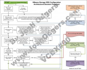
A collegue suggested a flowchart would assist in making the right decision around Storage DRS, so I took up the challenge to put one together.

The below is my version 0.1 of the flowchart, which I thought I would post and hopefully get some good feedback from the community, and create a good guide for those who may not have the in-depth knowledge or experience, too choose what should be in most cases an appropriate configuration for SDRS.

This also compliments some of my previous example architectural decisions which are shown in the related topic section below.

As always, feedback is always welcomed.

I hope you find this helpful.

* Updated to include the previously missing “NO” option for Data replication.

SDRS flowchart V0.2

Related Articles

1. Example Architectural Decision – Storage DRS configuration for NFS datastores

2. Example Architectural Decision – Storage DRS configuration for VMFS datastores