Data Locality & Why is important for vSphere DRS clusters

I have had a lot of people reach out to me since VMworld SFO, where I was interviewed by Eric Sloof (@esloof) on VMworldTV (interview can be seen here) about Nutanix.

So I thought I would expand on the topic of Data Locality and why it is so important for vSphere DRS clusters to maintain consistent high performance and low latency.

So first, the below diagram shows three (3) Nutanix nodes, and one (1) Guest VM.

NutanixLocalRead

The guest VM is reading data from the local storage in the Nutanix node and as a result this read access is very fast. The read I/O will be served from one of 4 places.

1. Extent Cache (DRAM – For “Active Working Set”)
2. Local SSD (For “Active Working Set”)
3. Local SATA (Only for “Cold” data)

and the forth we will discuss is a moment.

So as a result for Read I/O

1. There is no dependency on a Storage Area Network (FCoE, IP, FC etc)
2. Read I/O from one node does not contend with another node
3. Read I/O is very low latency as it does not leave the ESXi host
4. More Network bandwidth is available for Virtual Machine traffic, ESXi Mgmt, vMotion , FT etc

But wait, the what happens if DRS (or a vSphere admin) vMotion’s a VM to another node? – I’m glad you asked!

The below shows what happens immediately after a vMotion

NutanixAftervmotion

As you can see, only the Purple data is local to the new node, so transparently to the virtual machine, if/when remote data is required by the VM (ie: The VMs “Active Working Set”) the Nutanix controller VM (CVM) will get the requested data over the 10GB Network in 1MB extents. (It does not do a bulk movement or “Storage vMotion” type movement of all the VMs data EVER!)

And, all future Write I/O will be written local, so future Read I/O will all be local by default.

So, the worst case scenario for a read I/O in a Nutanix environment, is that the required data is not available locally and the CVM will access the data over a 10GB network.

This scenario will only occur in situations where

1. Maintenance is occurring and hosts are rebooted
2. A Host Failure (HA restarts VM on another node)
3. Following a vMotion

Generally in BAU (Business as Usual) operation Read I/O should be local in the high 90% range.

So the worst case scenario for Read I/O on a vSphere Cluster running on Nutanix, is actually the Best case scenario for a traditional storage array, because in a traditional array all data is accessed over some form of storage network and generally via a small number of controllers.

It is important to note, the Nutanix DFS (Distributed File System) only accesses data over the network when its required by the VM at a granular (1MB extent) level. So only the “Active Working Set” will be accessed over the 10Gb network, before being copied locally, again in 1MB extents. So if the data is not “Active” having it remotely does not impact performance at all so moving the data would create an overhead on the environment for no benefit.

In the event 90% of a VMs data is on a remote node, but the “Active Working Set” is local, read performance will all be at local speeds, again from Extent Cache (DRAM), Local SSD or Local SATA (for “cold” data).

Now some vendors are working on or have some local caching capabilities which in my experience are not widely deployed and have various caveats such as Operating System version, and in guest drivers, but for the vast majority of environments today, these technologies are not deployed.

The Nutanix DFS has data locality built in, it works with any hypervisor , Guest OS and does not require any configuration.

So now you know why ensuring the Active Working Set (data) is as close to the VM is essential for consistent high performance and low latency.

Related Articles

1. Write I/O Performance & High Availability in a scale-out Distributed File System

Example Architectural Decision – Datastore (LUN) Sizing with Block Based Storage

Problem Statement

In a vSphere environment, What is the most suitable Datastore (LUN) sizing to use for to support both production & development workloads to ensure minimum storage overhead and optimal performance?

Requirements

1. RTO 4hrs
2. RPO 12hrs
3. Support Production and Test & Development Workloads
4. Ensure optimal storage capacity utilization
5. Ensure storage performance is both consistent & maximized
6. Ensure the solution is fully supported
7. Minimize BAU effort (Monitoring)

Assumptions

1. Business critical applications are excluded
2. Block based storage
3. VAAI is supported and enabled
4. VADP backups are being utilized
5. vSphere 5.0 or later
6. Storage DRS will not be used
7. SRM is in use
8. LUNs & VMs will be thin provisioned
9. Average size VM will be 100GB and be 50% utilized
10. Virtual machine snapshot will be used but not for > 24 hours
11. Change rate of average VM is <= 15% per 24 hour period
12. Average VM has 4GB Ram
13. No Memory reservations are being used
14. Storage I/O Control (SOIC) is not being used
15. Under normal circumstances storage will not be over committed at the storage array level.
16. The average maximum IOPS per VMs is 125 (16Kb) (MBps per VM <=2)
17. The underlying storage has sufficient performance to cater for the average maximum IOPS per VM
18. A separate swap file datastore will be configured per cluster

Constraints

1. Must used existing storage solution (Block Based Storage)

Motivation

1. Increase flexibility
2. Ensure physical disk space is not unnecessarily wasted
3. Create a Scalable solution
4. Ensure high performance
5. Ensure high utilization of storage resources by reducing “islands” of unused capacity
6. Provide flexibility in the unit size of partial SRM failovers

Architectural Decision

The standard datastore size will be 3TB and contain up to 25 standard virtual machines.

This is based on the following

25 VMs per datastore X 100GB (Assumes no over commitment) = 2500GB

25 VMs w/ 4GB RAM = 100GB minus 0Gb reservation = 100GB vswap space to be stored on the swap file datastore

25 VMs w/ Snapshots of up to 15% =  375GB

Total = 2500GB + 375GB = 2875GB

Average capacity used per VM = 115GB

Justification

1. In worst case scenario where every VM has used 100% of its VMDK capacity and has 4GB RAM with no memory reservation and a snapshot of up to 15% of its size the 3TB datastore will still have 197GB remaining, as such it will not run out of space.
2. The Queue depth is on a per datastore (LUN) basis, as such, having 25 VMs per LUNs allows for a minimum of 1.28 concurrent I/O operations per VM based on the standard queue depth of 32 although it is unlikely all VMs will have concurrent I/O so the average will be much higher.
3. Thin Provisioning minimizes the impact of situations where customers demand a lot of disk space up front when they only end up using a small portion of the available disk space
4. Using Thin provisioning for VMs increases flexibility as all unused capacity of virtual machines remains available on the Datastore (LUN).
5. VAAI automatically raises an alarm in vSphere if a Thin Provisioned datastore usage is at >= 75% of its capacity
6. The impact of SCSI reservations causing performance issues (increased latency) when thin provisioned virtual machines (VMDKs) grow is unlikely to be an issue for 25 low I/O VMs and with VAAI is no longer an issue as the Atomic Test & Set (ATS) primitive alleviates the issue of SCSI reservations.
7. As the VMs are low I/O it is unlikely that there will be any significant contention for the queue depth with only 25 VMs per datastore
8. The VAAI UNMAP primitive provides automated space reclamation to reduce wasted space from files or VMs being deleted
9. Virtual machines will be Thin provisioned for flexibility, however they can also be made Thick provisioned as the sizing of the datastore (LUN) caters for worst case scenario of 100% utilization while maintaining free space.
10. Having <=25 VMs per datastore (LUN) allows for more granular SRM fail-over (datastore groups)

Alternatives

1.  Use larger Datastores (LUNs) with more VMs per datastore
2.  Use smaller Datastores (LUNs) with less VMs per datastore

Implications

1. When performing a SRM fail over, the most granular fail over unit is a single datastore which may contain up to 25 Virtual machines.

2. The solution (day 1) does not provide CapEx saving on disk capacity but will allow (if desired) over commitment in the future

Thanks to James Wirth (VCDX#83) @JimmyWally81 for his contributions to this example decision.

Related Articles

1. Datastore (LUN) and Virtual Disk Provisioning (Thin on Thick)

2. Datastore (LUN) and Virtual Disk Provisioning (Thin on Thin)

3. Virtual Machine vSwap Location

CloudXClogo


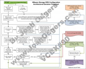
Storage DRS Configuration – Architectural Decision making flowchart

I was speaking to a number of people recently, who were trying to come up with a one size fits all Storage DRS configuration for a reference architecture document.

As Storage DRS is a reasonably complicated feature, it was my opinion that a one size fits all would not be suitable, and that multiple examples should be provided when writing a reference architecture.

A collegue suggested a flowchart would assist in making the right decision around Storage DRS, so I took up the challenge to put one together.

The below is my version 0.1 of the flowchart, which I thought I would post and hopefully get some good feedback from the community, and create a good guide for those who may not have the in-depth knowledge or experience, too choose what should be in most cases an appropriate configuration for SDRS.

This also compliments some of my previous example architectural decisions which are shown in the related topic section below.

As always, feedback is always welcomed.

I hope you find this helpful.

* Updated to include the previously missing “NO” option for Data replication.

SDRS flowchart V0.2

Related Articles

1. Example Architectural Decision – Storage DRS configuration for NFS datastores

2. Example Architectural Decision – Storage DRS configuration for VMFS datastores