Nutanix Resiliency – Part 4 – Converting RF3 to Erasure Coding (EC-X)

At this stage of the series the cluster has been converted from RF2 to RF3, now the customer want’s to get some capacity efficiency without impacting resiliency. We will now look at the process and speed of enabling Erasure Coding (EC-X).

As discussed in , Nutanix EC-X is performed as a background task and only on Write Cold data meaning the configured RF is completed as normal and then as a post process EC-X is performed to ensure the write process is not potentially slowed by requiring numerous nodes within the cluster to participate in the initial write I/O.

For more detailed information on Nutanix EC-X implimentation, see my Nutanix – Erasure Coding (EC-X) Deep Dive.

What I/O will Nutanix Erasure coding (EC-X) take effect on? Good question, only Write cold data. As such, EC-X savings are realised over time as data becomes cold and as Nutanix ADSF curator scans to perform the background conversion as a low priority task.

How fast does ADSF convert RF2/3 to EC-X stripes? In short, we can do this as fast as the underlying drives can handle as shown in earlier parts of this series, but as EC-X is a space saving technology, it does not make sense to drive it as fast as say a node or drive failure operation as no data is at risk.

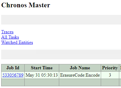
So under the covers the “ErasureCode:Encode” task is a Priority 3 as shown below, whereas a node/disk failure task is priority 1.

ECXPriority3Tasks

In cases where a customer wishes to encode their data as fast as possible this can be achieved in many way, including by enabling “curator maintenance mode” which basically removes soft limits and allows curator to drive as much background I/O as the cluster can handle, but this should only be used under supervision of Nutanix support so I won’t be sharing how to do this publicly.

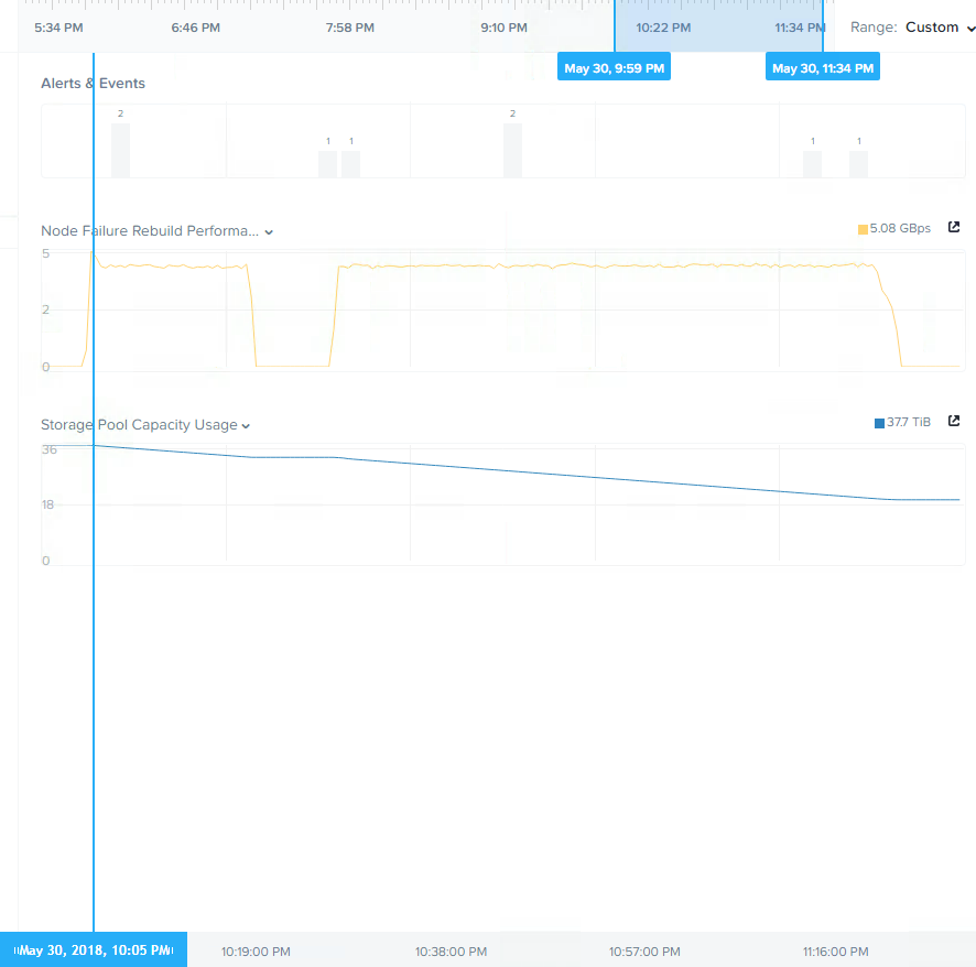
Below is the throughput and storage pool usage after applying EC-X. The reason for the dip in the middle is because I enabled EC-X part way through a background curator scan which meant only some data was converted and then I manually trigged another curator full scan which completed the job at a very high and consistent rate of >5GBps.

ECXsavingsAndStoragePoolCapacityUsage

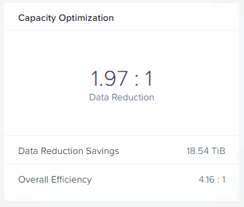
The below is the resulting capacity optimisation of 1.97:1 which is almost the theoretical maximum of 2:1. The reason EC-X was able to achieve near the maximum is there is no active workload on the cluster during this testing and as a result all the data is “write cold” and available for EC-X to stripe.

EC-XSavingsCompletedMultipleScans

So we have read the entire dataset of around 37.7TB and re-written the data in 4+2 EC-X stripes (4 data, 2 parity) which used around 18TB of space. This resulted in a saving of 18.54TB of physical storage.

If we do some simple math, we have 37.7TB of data read by ADSF and 18TB of EC-X stripes written for a total of approx 56TB of IO serviced by ADSF in less than 90mins.

Summary:

  • Nutanix EC-X has no additional write penalty compared to RF3 ensuring optimal write performance while providing up to 2x capacity efficiency at the same resiliency level.
  • ADSF uses it’s distributed storage fabric to efficiently stripe data
  • Background EC-X striping is a low priority task to minimise the impact on front end virtual machine IO
  • ADSF can sustain very high throughput during EC-X (background) operations
  • Using RF3 and EC-X ensures maximum resiliency and capacity efficiency resulting in up to 66% usable capacity of RAW storage (up to 2:1 efficiency over RF3)

Index:
Part 1 – Node failure rebuild performance
Part 2 – Converting from RF2 to RF3
Part 3 – Node failure rebuild performance with RF3
Part 4 – Converting RF3 to Erasure Coding (EC-X)
Part 5 – Read I/O during CVM maintenance or failures
Part 6 – Write I/O during CVM maintenance or failures
Part 7 – Read & Write I/O during Hypervisor upgrades
Part 8 – Node failure rebuild performance with RF3 & Erasure Coding (EC-X)
Part 9 – Self healing
Part 10: Nutanix Resiliency – Part 10 – Disk Scrubbing / Checksums

Nutanix Resiliency – Part 2 – Converting from RF2 to RF3

In part 1 we discussed the ability of Nutanix AOS to rebuild from a node failure in a fast and efficient manner thanks to the Acropolis Distributed Storage Fabric (ADSF). In part 2 I wanted to show how a storage container can be converted from RF2 to RF3 and the speed at which the operation can be completed.

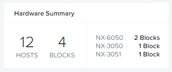
For this testing, only 12 nodes exist within the cluster.

ClusterSize

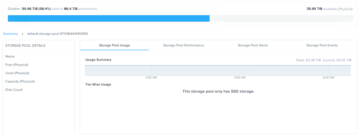
Let’s start with the storage pool capacity usage.

RF2Usage

Here we see just over 50TB of storage usage across the cluster.

In converting to RF3, or put simply adding a third replica of all data, we need to ensure we have enough available capacity otherwise RF3 wont be in compliance.

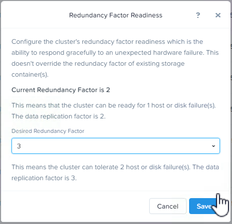
Next we increase the Redundancy Factor for the cluster (and metadata) to RF3. This enables the cluster to support RF3 containers, and to survive at least two node failures from a metadata perspective.

ReducdancyFactorCLuster

Next we increase the desired Storage Container to RF3.

Once the container is set to RF3, curator will detect the cluster is not in compliance with the configured redundancy factor and kick of a background task to create the additional replicas.

In this case, we started with approx 50TB of data in the storage pool, so this task will need to create 50% more replicas so we should end up with around 75TB of data.

Let’s see how long it took the cluster to create 25TB of data to comply with the new Redundancy Factor.

RF2toRF3on12NodeCluster

Here we see throughput of over 7GBps and the process taking less than 3 hours, so approx 8.3TB per hour. It is important to note that the cluster remained fully resilient at an RF2 level throughout the whole process, and had new writes been happening during this phase, they would all be protected with RF3.

Below is a chart showing the storage pool capacity usage increasing in a very linear fashion throughout the operation.

StoragePoolCapacityGrowth

Had the cluster been larger, it is important to note this task would have performed faster, as ADSF is a truely distributed storage fabric and the more node, the more controllers than participate in all write activity. For a great example of the advantage of adding additional nodes check out Scale out performance testing with Nutanix Storage Only Nodes.

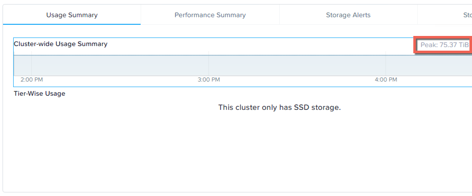
Once the operation was completed we can see the storage pool capacity usage is at the expected 75TB level.

StoragePoolCapacityWithRF3

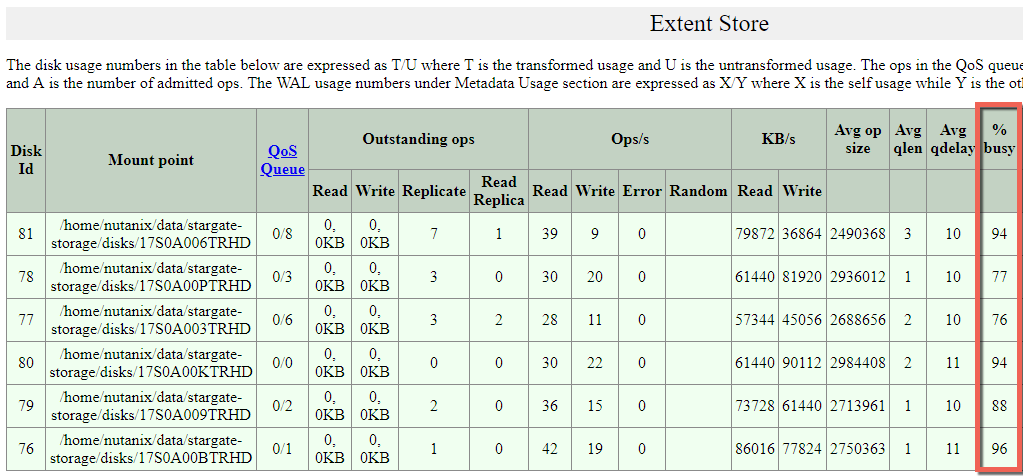
For those who are interested how hard Nutanix ADSF can drive the physical drives, I pulled some stats during the compliance phase.

StargateExtentStoreStats

What we can see highlighted is that the physical drives are being driven at or close to their maximum and the read and write I/O is being performed across all drives, not just to a single cache drive and then offloaded to capacity drives like less intelligent HCI platforms.

Summary:

  • Nutanix ADSF can change between Redundancy levels (RF2 and RF3) on the fly
  • A compliance operation creating >25TB of data can complete in less than 3 hours (even on 5 year old equipment)
  • The compliance operation performed in a linear manner throughout the task.
  • A single Nutanix Controller VM (CVM) is efficient enough to drive 6 x physical SSDs at close to their maximum ability
  • ADSF reads and writes to all drives and does not use a less efficient cache and capacity style architecture.

Index:
Part 1 – Node failure rebuild performance
Part 2 – Converting from RF2 to RF3
Part 3 – Node failure rebuild performance with RF3
Part 4 – Converting RF3 to Erasure Coding (EC-X)
Part 5 – Read I/O during CVM maintenance or failures
Part 6 – Write I/O during CVM maintenance or failures
Part 7 – Read & Write I/O during Hypervisor upgrades
Part 8 – Node failure rebuild performance with RF3 & Erasure Coding (EC-X)
Part 9 – Self healing
Part 10: Nutanix Resiliency – Part 10 – Disk Scrubbing / Checksums