RF2 & RF3 Usable Capacity with Erasure Coding (EC-X)

Over the past few weeks with the release of Acropolis base version 4.5 (formally known as NOS) on the horizon there has been a lot of interest in Erasure Coding (EC-X) which was announced at Nutanix .NEXT conference in June this year.

The most common questions are how does EC-X increase the effective SSD tier capacity and the overall cluster usable capacity. This post aims to cover these questions.

Resiliency Factor 2 (RF2) & Erasure Coding

Resiliency Factor 2 ensures that two copies of all data are written to persistent media prior to being acknowledged to the guest operating system. This ensures at N+1 level of redundancy which translates to being able to tolerate a single failure.

RF2 provides a usable capacity of ~50% of RAW.

The below figure shows an example of RF2 where six blocks store three pieces of data in a redundant fashion. In this configuration a single SSD/HDD or node can be lost without impacting data availability.

RF2normal

Now let’s take a look at how the same 6 blocks will be utilized with Erasure Coding enabled:

RF2plusECX

As we can see, we are now able to store four pieces of data (A,B,C,D) with single parity to ensure data can be rebuilt in the event of a drive or node failure. As with standard RF2, an RF2 + EC-X configuration can also tolerate a single SSD/HDD or node can be lost without impacting data availability. We also free up space to be used for another EC-X stripe.

As a result, the usable capacity increases from approx. 50% usable up to 80% usable for clusters of six (6) or larger.

The following table shows the maximum usable capacity for RF2 + EC-X based on cluster size:

Note: Assumes 20TB RAW per node

RF2table

Resiliency Factor 3 (RF3) & Erasure Coding

Resiliency Factor 3 ensures that three copies of all data are written to persistent media prior to being acknowledged to the guest operating system. This ensures at N+2 level of redundancy which translates to being able to tolerate two concurrent SSD/HDD or node failures.

RF3 provides a usable capacity of ~33% of RAW.

The below figure shows an example of RF3 where six blocks store two pieces of data in a redundant fashion. In this configuration the environment can tolerate two concurrent SSD/HDD or node failures without impacting data availability.

RF3normal

Now let’s take a look at how the same 6 blocks will be utilized with Erasure Coding enabled:

RF3ECX

Similar to the RF2 example, we can see we are now able to store more data with the same level of redundancy. In this case, five pieces of data (A,B,C, D) with dual parity to ensure data can be rebuilt in the event of dual concurrent drive or node failures. As with standard RF3, an RF3 + EC-X provides an N+2 level of availability while providing higher usable capacity.

The following table shows the usable capacity for RF3 + EC-X based on cluster size:

Note: Assumes 20TB RAW per node

RF3ECXtable

EC-X Parity Placement

To further increase the effective capacity of the SSD tier and there for supporting larger working set sizes with all flash performance, the Parity for containers with EC-X enabled is stored on the SATA tier.

The following figure shows a standard RF3 deployment:
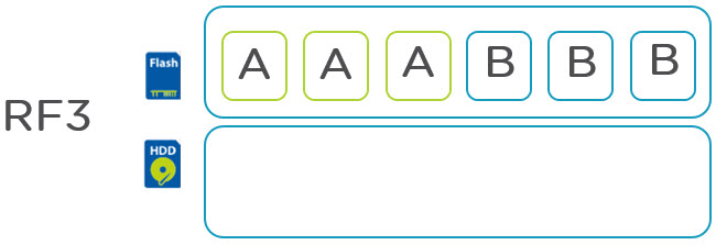
RF3parityNormal

As we can see, 6 blocks of storage contain just 2 actual pieces of user data all of which reside in the SSD tier.

With RF3 + EC-X the same 6 blocks of storage contain 4 pieces of user data thus increasing the effective capacity of the SSD tier by 100% due to being able to store 4 piece of data compare to two with RF3. In addition the effective SSD capacity is further increased by moving the 2 parity blocks to SATA freeing up a further 33% SSD tier capacity.

RF3ECXparity

I hope that explains how EC-X works and why its such an advantage for Nutanix current and futures customers.

Related Articles:

  1. Nutanix Erasure Coding Deep Dive
  2. Increasing resiliency of large clusters with Erasure Coding
  3. What I/O will EC-X take effect on?
  4. Sizing assumptions for solutions with Erasure Coding (EC-X)


What I/O will Nutanix Erasure coding (EC-X) take effect on?

In recent weeks I have been presenting at a number of Nutanix .NEXT roadshow events and I was asked a good question about Erasure Coding (EC-X) at the Melbourne event which I felt justified a quick post.

The question was along the lines of:

How does Erasure Coding affect Write intensive workloads?

The question came following a statement I made which was to the effect of enabling RF3 + Erasure Coding may prove to be an excellent default container configuration when talking about resiliency and capacity optimization.

So let’s take a look at the Write path for a Nutanix XCP environment with EC-X enabled:

ECXprocess

Step 1: Confirm the data resiliency being RF2 or RF3 (FTT1 / FTT2 in other vendor speak)

Step 2: Is the I/O random or sequential

Step 3: Is the Data Write Hot?

This is where we start talking about EC-X and one of the areas where Nutanix patent pending algorithm shines. The XCP monitors the data and when the data is write hot, EC-X will not be performed on that data and the blocks (or “extents” in Nutanix Distributed File System speak) will remain in the SSD tier.

Step 4: If the data is not Write Hot, perform EC-X on the data.

Step 5: Is the data Read hot?

What do I mean by read hot? Basically is the data being read frequently (but not overwritten). If it is Read Hot, the data will remain in the SSD tier having previously been striped by EC-X.

As a result, more data can now fit into the SSD tier giving better overall performance for a larger working set.

Step 6: If the data is not Read Hot (and not write hot) it will be a candidate for migration to the low cost SATA tier via Nutanix ILM (Intelligent Life-cycle Management) process which runs in real time (not on a scheduled basis).

So will a write intensive workloads performance be degraded if EC-X is enabled?

Short answer: No

If the container where the write intensive workload is running is configured with EC-X, the data which is write intensive will simply not be subject to EC-X as the platform understands and monitors the data and only applied EC-X if the data becomes write cold.

So the good news is, even if you enable EC-X it will not impact write intensive workloads, but it will provide capacity savings and an effective increase in usable SSD tier for the data which is Write Cold, Read Hot/Cold.

Storage I/O Control (SIOC) configuration for Nutanix

Storage I/O Control (SIOC) is a feature introduced in VMware vSphere 4.1 which was designed to allow prioritization of storage resources during periods of contention across a vSphere cluster. This situation has often been described as the “Noisy Neighbor” issue where one or more VMs can have a negative impact on other VMs sharing the same underlying infrastructure.

For traditional centralized shared storage, enabling SIOC is a “No Brainer” as even using the default settings will ensure more Consistent performance during periods of storage contention which all but no downsides. SIOC does this by managing and potentially throttling the Device Queue depth based on “Shares” assigned to each Virtual Machine to ensure Consistent performance across ESXi hosts.

The below diagrams show the impact on three (3) identical VMs with the same Disk “Shares” values with and without SIOC in a traditional centralized storage environment (a.k.a SAN/NAS).

Without Storage I/O Control

NutanixWithoutSIOC

With Storage I/O Control

NutanixWithSIOC


As show in the above, where VMs have equal share values but reside on different ESXi hosts can result in an undesired result with one VM having double the available storage queue compared to the VMs residing on a different host.  In comparison, SIOC ensuring VMs with the same share value get equal access to the underlying storage queue.

While SIOC is an excellent feature, it was designed to address a problem which is no longer a significant factor with the Nutanix Scale out Shared nothing style architecture.

The issue of “noisy neighbour” or storage contention in the Storage Area Network (SAN) is all but eliminated as all Datastores (or “Containers” in Nutanix speak) are serviced by every Nutanix Controller VM in the cluster and under normal circumstances, upwards on 95% of read I/O is serviced by the local Controller VM, Nutanix refers to this feature as “Data Locality”.

Data Locality ensures data being written and read by a VM remains on the Nutanix node where the VM is running, thus reducing latency of accessing data across a Storage Area Network, and ensuring that a VM reading data on one node, has minimal or no impact on another VM on another node in the cluster.

As Write I/O is also distributed throughout the Nutanix cluster, which means no one single node is monopolized by (Write) replication traffic.

Storage I/O Control was designed around the concept of a LUN or NFS mount (from vSphere 5.0 onwards) where the LUN or NFS mount is served by a central storage controller, as is the most typical deployment in the past for VMware vSphere environment.

As such, SIOC limiting the LUN queue depth allowed all VMs on the LUN to have either an equal share of the available queue, OR by specifying “Share” values on a VM basis, ensure VMs can be prioritized based on importance.

By default, all Virtual Hard Disks have a share value of “Normal” (1000 shares). Therefore if a individual VM needs to be given higher storage priority, the Share value can be increased.

Note: In general, modifying VM Virtual disk share values should not be required.

As Nutanix has one Storage Controller (or CVM) per node which all actively service I/O to the Datastore, SOIC is not required, and provides no benefits.

For more information about SIOC in traditional NAS environments see: “Performance implications of Storage I/O Control – Enabled NFS Datastores in VMware vSphere 5.0

As such for Nutanix environments it is recommended SIOC control be disabled and DRS “anti-affinity” or “VM to host” rules be used to separate high I/O VMs.