How to successfully Virtualize MS Exchange – Part 10 – Presenting Storage direct to the Guest OS

Let’s start with listing three common storage types which can be presented direct to a Windows OS?

1. iSCSI LUNs
2. SMB 3.0 shares
3. NFS mounts

Next let’s discuss these 3 options.

iSCSI LUNs are a common way of presenting storage direct to the Guest OS even in vSphere environments and can be useful for environments using storage array level backup solutions (which will be discussed in detail in an upcoming post).

The use of iSCSI LUNs is fully supported by VMware and Microsoft as iSCSI meets the technical requirements for Exchange, being Write Ordering, Forced Unit Access (FUA) and SCSI abort/reset commands. iSCSI LUNs presented to Windows are then formatted with NTFS which is a journalling file system which also protects against Torn I/O.

In vSphere environments nearing the configuration maximum of 256 datastores per ESXi host (and therefore HA/DRS cluster) presenting iSCSI LUNs to applications such as Exchange can help ensure scalability even where vSphere limits may have been reached.

Note: I would recommend reviewing the storage design and trying to optimize VMs/LUN etc first before using iSCSI LUNs presented to VMs.

The problem with iSCSI LUNs is they result in additional complexity compared to using VMDKs on Datastores (discussed in Part 11). The complexity is not insignificant as typically multiple LUNs need to be created per Exchange VM, things like iSCSI initiators and LUN masking needs to be configured. Then when the iSCSI initiator driver is updated (say via Windows Update) you may find your storage disconnected and you may need to troubleshoot iSCSI driver issues. You also need to consider the vNetworking implications as the VM now needs IP connectivity to the storage network.

I wrote this article (Example VMware vNetworking Design w/ 2 x 10GB NICs for IP Storage) a while ago showing an example vNetworking design that supports IP storage with 2 x 10GB NICs.

The above article shows NFS on the dvPortGroup name but the same configuration is also optimal for iSCSI. Each Exchange VM would then need a 2nd vmNIC connected to the iSCSI portgroup (or dvPortgroup) ideally with a static IP address.

IP addressing is another complexity added by presenting storage direct to VMs rather than using VMDKs on datastores.

Many system administrators, architects and engineers might scoff at the suggestion iSCSI is complex, but in my opinion while I don’t find iSCSI at all difficult to design/install/configure and use, it is significantly more complex and has many more points of failure than using a VMDK on a Datastore.

One of the things I have learned and seen benefit countless customers over the years is keeping things as simple as possible while meeting the business requirements. With that in mind, I recommend only considering the use of iSCSI direct to the Guest OS in the following situations:

1. When using a Backup solution which triggers a storage level snapshot which is not VM or VMDK based. i.e.: Where snapshots are only support at the LUN level. (Older storage technologies).
2. Where ESXi scalability maximums are going to be reached and creating a separate cluster is not viable (technically and/or commercially) following a detailed review and optimization of storage for the vSphere environment.
3. When using legacy storage architecture where performance is constrained at a datastore level. e.g.: Where increasing the number of VMs per Datastore impacts performance due to latency created from queue depth or storage controller contention.

Next let’s discuss SMB 3.0 / CIFS shares.

SMB 3.0 or CIFS shares are commonly used to present storage for Hyper-V and also file servers. However presenting SMB 3.0 directly to Windows is not a supported configuration for MS Exchange because SMB 3.0 presented to the Guest OS directly does not meet the technical requirements for Exchange, such as Write Ordering, Forced Unit Access (FUA) and SCSI abort/reset commands.

However SMB 3.0 is supported for MS Exchange when presented to Hyper-V and where Exchange database files reside within a VHD which emulates the SCSI commands over the SMB file protocol. This will be discussed in the upcoming Hyper-V series.

The below is a quote from Exchange 2013 storage configuration options outlining the storage support statement for MS Exchange.

All storage used by Exchange for storage of Exchange data must be block-level storage because Exchange 2013 doesn’t support the use of NAS volumes, other than in the SMB 3.0 scenario outlined in the topic Exchange 2013 virtualization. Also, in a virtualized environment, NAS storage that’s presented to the guest as block-level storage via the hypervisor isn’t supported.

The above statement is pretty confusing in my opinion, but what Microsoft mean by this is SMB 3.0 is supported when presented to Hyper-V with Exchange running in a VM with its databases housed within one or more VHDs. However to be clear presenting SMB 3.0 direct to Windows for Exchange files is not supported.

NFS mounts can be used to present storage to Windows although this is not that common. Its important to note presenting NFS directly to Windows is not a supported configuration for MS Exchange and as with SMB 3.0, presenting NFS to Windows directly also does not meet the technical requirements for Exchange, being Write Ordering, Forced Unit Access (FUA) and SCSI abort/reset commands. iSCSI LUNs can be formatted with VMFS which is a journalling file system which also protects against Torn I/O.

As such I recommend not presenting NFS mounts to Windows for Exchange storage.

Note: Do not confuse presenting NFS to Windows which presenting NFS datastores to ESXi as these are different. NFS datastores will be discussed in Part 11.

Summary:

iSCSI is the only supported storage protocol to present storage direct to Windows for storage of Exchange databases.

Lets now discuss the Pros and Cons for presenting iSCSI storage direct to the Guest OS.

PROS

1. Ability to reduce overheads of legacy LUN based snapshot based backup solutions by having MS Exchange use dedicated LUN/s therefore reducing delta changes that need to be captured/stored. (e.g.: Netapp SnapManager for Exchange)
2. Does not impact ESXi configuration maximums for LUNs per ESXi host as storage is presented to the Guest OS and not the hypervisor
3. Dedicated LUN/s per MS Exchange VM can potentially improve performance depending on the underlying storage capabilities and design.

CONS

1. Complexity e.g.: Having to create, present and manage LUN/s per Exchange MBX/MSR VMs
2. Having to manage and potentially troubleshoot iSCSI drivers within a Guest OS
3. Having to design for IP storage traffic to access VMs directly, which requires additional vNetworking considerations relating to performance and availability.

Recommendations:

1. When choosing to present storage direct to the Guest OS, only iSCSI is supported.
2. Where no requirements or constraints exist that require the use of storage presented to the Guest OS directly, use VMDKs on Datastores option which is discussed in Part 11.
3. Use a dedicated vmNIC on the Exchange VM for iSCSI traffic
4. Use NIOC to ensure sufficient bandwidth for iSCSI traffic in the event of network congestion. Recommended share values along with justification can be found in Example Architectural Decision – Network I/O Control Shares/Limits for ESXi Host using IP Storage.
5. Use a dedicated VLAN for iSCSI traffic
6. Do NOT present SMB 3.0 or NFS direct to the Guest OS and use for Exchange Databases!

Back to the Index of How to successfully Virtualize MS Exchange.

Ensuring Data Integrity with Nutanix – Part 2 – Forced Unit Access (FUA) & Write Through

In the Integrity of Write I/O for VMs on NFS Datastores Series, I discussed Forced Unit Access (FUA) and Write Through in part 2 which covered a vendor agnostic view of FUA and Write through.

In this series, The goal is too explain how Nutanix can guarantee data integrity and how this is Nutanix Number #1 priority. In addition to this goal, I want to show how Nutanix supports Business Critical Applications such as MS SQL and MS Exchange which have strict storage requirements such as Write Ordering, Forced Unit Access (FUA) , SCSI abort/reset commands and to protect against Torn I/O.

Note: With Windows 2012 onwards FUA is no longer used in favour of issuing a “Flush” of the drives write cache. However this change makes no difference to Nutanix environments because regardless of FUA or a Flush being used, write I/O is not acknowledged until written to persistent media on 2 or more nodes which will be explained further later in this post.

Currently MS Exchange is not supported to run in a VMDK on an NFS datastore/s although interestingly Active Directory and MS SQL servers which have the exact same storage requirements (discussed earlier) are supported. This post will show why Microsoft should allow storage vendors to certify Exchange in a VMDK on NFS datastore deployments to prove compliance with the storage requirements stated earlier.

Note: Nutanix provides support for Exchange 2010/2013 deployments in VMDKs on NFS datastores. Customers can find this support statement on http://portal.nutanix.com/ under article number 000001303.

Firstly I would like to start by stating that FUA is fully supported by VMware ESXi.

In the Microsoft article, Deploying Transactional NTFS, it states:

“The caching control mechanism used by TxF is a flag known as the Force Unit Access (FUA) function. This flag specifies that the drive should write the data to stable media storage before signaling complete.”

Nutanix meets this requirement as all writes are written to persistent media (SSD) on at least two independent nodes and no write caching is performed at any layer including the Nutanix Controller CM (CVM), Physical Storage Controller card or the physical drives themselves.

For more information on how Nutanix is compliant with this requirement click here.

The article also states:

“Some Host Bus Adapters (HBAs) and storage controllers (for example, RAID systems) have built-in battery-backed caches. Because these devices preserve cached data if a power fault occurs, any disks connected to them are not required to honor the FUA flag. Further, a disk whose power supply is protected by an uninterruptable power supply (UPS) does not need to honor the FUA flag. This is because the UPS will maintain power long enough for the disk to flush its cache to the media.”

As discussed with the previous requirement, Nutanix meets this requirement as the write acknowledgement is not given until writes are successfully commited to persistent storage on at least two nodes. As a result, even without a UPS, data integrity can be guaranteed in a Nutanix environment.

For more information on how Nutanix is compliant with this requirement click here.

Another key point in the article is:

“Disabling a drive’s write cache eliminates the requirement for the drive to honor the FUA flag.”

All physical drives (SSD and SATA) in a Nutanix nodes have their write cache disabled, therefore removing the requirement of FUA.

The article concludes with the following:

“Note  For TxF to be capable of consistently protecting your data’s integrity through power faults, the system must satisfy at least one of the following criteria:


1. Use server-class disks (SCSI, Fiber Channel)

2. Make sure the disks are connected to a battery-backed caching HBA.

3. Use a storage controller (for example, RAID system) as the storage device.

4. Ensure power to the disk is protected by a UPS.

5. Ensure that the disk’s write caching feature is disabled.”

We have already discussed because Nutanix does not use a non persistent write cache there is no requirement for the OS to issue the FUA flag or the Flush command in Windows 2012 to ensure data is written to persistent media. But for fun lets see how many of the above Nutanix is compliant with.

1. YES – Nutanix uses enterprise grade Intel S3700 SSDs for all write I/O
2. N/A – There is no need for battery backed caching HBAs due to Nutanix write acknowledgement not being given until written to persistent media on two or more nodes
3. YES – Nutanix Distributed File System (NDFS) with Resiliency Factor (RF) 2 or 3
4. Recommended to ensure system uptime but not required to ensure data integrity as writes are not acknowledged until written to persistent media on two or more nodes
5. YESAll write caching features are disabled on all SSDs/HDDs

So to meet Microsoft’s FUA requirements, only one of the above is required. Nutanix meets 3 out of 5 outright, with a 4th being Recommended (but not required) and the final requirement not being applicable.

Write Cache and Write Acknowledgements.

Nutanix does not use a non persistent write cache, period.

When a I/O is issued in a Nutanix environment, if it is Random, it will be sent to the “OpLog” which is a persistent write buffer stored on SSD.

If the I/O is sequential, it is sent straight to the Extent Store which is persistent data storage, also located on SSD.

Both Random and Sequential I/O flows are shown in the below diagram from The Nutanix Bible by @StevenPoitras.

NDFS_IO_basev5

All Writes are also protected by Resiliency Factor (RF) of 2 or 3, meaning 2 or 3 copies of the data are synchronously replicated to other Nutanix nodes within the cluster prior to the write being acknowledged.

To be clear, Write acknowledgements are NOT sent until the data is written to 2 or 3 nodes OpLog or Extent Store (depending on the configured RF). What this means is the requirement for Forced Unit Access (FUA) is achieved as every write is written to persistent media before write acknowledgements are sent regardless of FUA (or Flush) being issued by the OS.

Importantly, this write acknowledgement process is the same regardless of the storage protocol (iSCSI , NFS , SMB 3.0) used to present storage to the hypervisor (ESXi , Hyper-V or KVM).

Physical Drive Configuration

As Nutanix does not use a non persistent write cache, and does not acknowledge writes until written to persistent media on 2 or 3 nodes, that’s the end of the problem right?

Not really, as physical drives also have write caches and in the event of a power failure, its possible (albeit unlikely) data in the cache may not be written to disk even after a write acknowledgement is written.

This is why all physical SSD / SATA drives in a Nutanix environment have the disks write caching feature disabled.

This ensures there is no dependency on Uninterruptable power supplies (UPS) to ensure data is successfully written to the disk in the event of a power failure.

This means Nutanix is compliant with the “Ensure that the disk’s write caching feature is disabled” requirement specified by Microsoft.

Uninterruptible Power Supplies (UPS)

As non persistent write caching is not used either at the Nutanix Controller VM (CVM), Physical Storage Controller OR the physical SSDs/HDDs, the use of a UPS is not a requirement for a Nutanix environment to ensure data integrity, however it is still recommended to use a suitable UPS to ensure uptime of the environment. Assuming a power outage is not catastrophic (e.g.: For a single node) and the cluster is still online, write acknowledgements are still not given until data is written to the configured RF policy as Nutanix nodes are effectively stateless.

The Microsoft article quoted earlier states:

“Further, a disk whose power supply is protected by an uninterruptable power supply (UPS) does not need to honor the FUA flag. This is because the UPS will maintain power long enough for the disk to flush its cache to the media.”

Even in the case a storage solution or disk is protected by a UPS, it requires sufficient time to allow all data in the cache to be written to persistent media. This is a potential risk to data consistency as a UPS is just another link in the chain which can go wrong. This is why Nutanix does not depend on UPS for data integrity.

Another Microsoft Article, Key factors to consider when evaluating third-party file cache systems with SQL Server gives two examples of how data corruption can occur:

“Example 1: Data loss and physical or logical corruption”

“Example 2: Suspect database”

So how does Nutanix protect against these issues?

The article states

“How to configure a product providing file cache from something like non-battery backed cache is specific to the vendor implementation. A few rules, however, can be applied:

1. All writes must be completed in or on stable media before the cache indicates to the operating system that the I/O is finished.

2. Data can be cached as long as a read request serviced from the cache returns the same image as located in or on stable media.”

Regarding the first point: All write I/O is written to persistent media (as is the intention of FUA) as described earlier in this article.

For the second point, the Nutanix Distributed File System (NDFS) read I/O can happen from one of the following places:

  1. “Extent Cache”, located in RAM.
  2. “Content Cache”, located on SSD as per earlier diagram.
  3. “Oplog”, the persistent write cache located on SSD as per earlier diagram.
  4. “Extent store” located on either SSD or SATA depending on if the data is “Hot” or ‘Cold”.
  5. A remote nodes Extent Cache, Content Cache, OpLog or Extent Store

To ensure the Extent Cache (in RAM) is consistent with the Content Cache or Extent Store located on the persistent media, when a write I/O occurs which modifies data which has been cached in the Extent Cache (in RAM), the corresponding data is discarded from the Extent Cache and only promoted back to the Extent Cache if the data profile remains Hot (i.e.: Frequently accessed).

In Summary:

The Nutanix write path guarantees (even without the use of a UPS) writes are written to persistent media and have at least 1 redundant copy on another node in the cluster for resiliency before acknowledging the I/O back to the hypervisor and onto the guest. This is critical to ensuring data consistency/resiliency.

This is in full compliance with the storage requirements of applications such as SQL, Exchange and Active Directory.

——————————————————–

Integrity of Write I/O for VMs on NFS Datastores Series

Part 1 – Emulation of the SCSI Protocol
Part 2 – Forced Unit Access (FUA) & Write Through
Part 3 – Write Ordering
Part 4 – Torn Writes
Part 5 – Data Corruption

Nutanix Specific Articles

Part 6 – Emulation of the SCSI Protocol (Coming soon)
Part 7 – Forced Unit Access (FUA) & Write Through
Part 8 – Write Ordering (Coming soon)
Part 9 – Torn I/O Protection (Coming soon)
Part 10 – Data Corruption (Coming soon)

Related Articles

1. What does Exchange running in a VMDK on NFS datastore look like to the Guest OS?
2. Support for Exchange Databases running within VMDKs on NFS datastores (TechNet)
3. Microsoft Exchange Improvements Suggestions Forum – Exchange on NFS/SMB
4. Virtualizing Exchange on vSphere with NFS backed storage

Deduplication ratios – What should be included in the reported ratio?

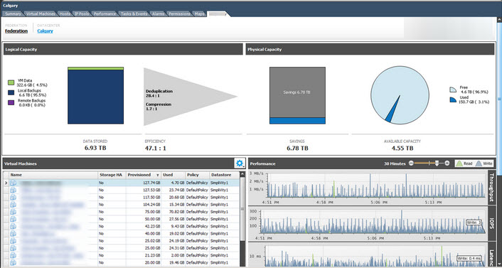
I saw the below picture posted on Twitter, and there has been some discussion around the de-duplication ratio (shown below as an an amazing 28.4:1) and what this should and should not include.

03-Jan-15 12-39-25 PMA

In the above case, this ratio includes VM snapshots or what some people in my opinion incorrectly refer to as “backups” (But that’s a topic for another post). In other storage solutions, things like savings from intelligent cloning may also be included.

First l’d like to briefly explain what de-duplication means to me.

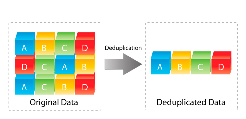
I think the below diagram really sums it up well. If 12 pieces of data exist (ie: Have been written or are in the process of being written in the case of in-line de-duplication) to the storage layer, de-duplication (in-line or post process) removes the duplicate data and uses pointers to direct duplicates back to a single copy rather than storing duplicates.

deduplication_diagram

The above image is courtesy of www.enterprisestorageguide.com.

In the above example, the original data has 12 blocks which have been de-duplicated down to 4 blocks.

With this in mind, what should be included in the de-duplication ratio?

The following are some ways to reduce data consumption which in my opinion add value to a storage solution:

1. De-duplication (In-line or post process)
2. Intelligent cloning i.e.: Things like VAAI-NAS Fast File Clone, VCAI, FlexClone etc
3. Point in time snapshot recovery points. (As they are not backups until stored elsewhere)

Obviously, if data that exists or is being written to a storage system and its de-duplicated in-line or post process, this data reduction should be included in the ratio. I’d be more than a little surprised if anyone disagreed on this point.

The one exception to this is where VMDKs are Eager Zeroed Thick (EZT) and de-duplication is simply removing 0’s which in my opinion is simply putting additional load on the storage controllers and over inflating the de-duplication ratio when thin provisioning can be used.

For storage solutions de-duplicating zeros from EZT VMDKs, these capacity savings should be called out as a separate line item. (Discussed later in this post).

What about Intelligent cloning? Well the whole point of intelligent cloning is not to write or have the storage controllers process duplicate data in the first place. So based on this, VMs which are intelligently cloned are not deduped as duplicate data is never written or processed.

As such its my opinion Intelligent cloning savings should not be included in the de-duplication ratio.

Next lets talk “point in time snapshot recovery points“.

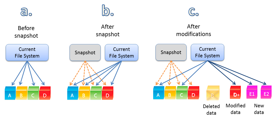
The below image shows the VM before a snapshot (a.) has blocks A,B,C & D.

Then after a snapshot without modifications, the VM has the same blocks A,B,C & D.

Then finally, when the VM makes modifications to or deletes data after the snapshot, we see the A,B,C & D remain in tact thanks to the snapshot but then we have a deleted item (B) then modified data (D+) along with net new data E1 & E2.

Feature-Snapshots-Full

Image courtesy of www.softnas.com.

So savings from snapshots are also not “de-duplicating” data, they are simply preventing new data being written, much like intelligent cloning.

As with Intelligent cloning savings, my opinion is savings from snapshots should not be included in the de-duplication ratio.

Summary

In my opinion, the de-duplication ratio reported by a storage solution should only include data which has been written to disk (post process), or was in the process of being written to disk (in-line) that has been de-duplicated.

But wait there’s more!

While I don’t think capacity savings from Intelligent cloning and snapshots should be listed in the de-duplication ratio, I think these features are valuable and the benefits of these technologies should be reported.

I would suggest a separate ratio be reported, for example, Data Reduction.

The Data reduction ratio could report something like the following where all capacity savings are broken out to show where the savings come from:

1) Savings from Deduplication: 2.5:1 (250GB)
2) Savings from Compression: 3:1 (300GB)
3) Savings from Intelligent Cloning: 20:1 (2TB)
4) Savings from Thin Provisioning: 50:1 (5TB)
5) Savings from Point in time Snapshots: 30:1 (3TB)
6) Savings from removal of zeros in EZT VMDKs: 100:1 (10TB)

Then the Total data reduction could be listed e.g.: 60.5:1 (20.7TB)

For storage solutions, the effective capacity of each storage tiers (Memory/SSD/HDD) for example could also be reported as a result of the data reduction savings.

This would allow customers to compare Vendor X with Vendor Y’s deduplication or compression benefits, or compare a solution which can intelligently clone with one that cannot.

Conclusion: 

The value of deduplication, point in time snapshots and intelligent cloning in my mind are not in question, and I would welcome a discussion with anyone who disagrees.

I’d hate to see a customer buy product “X” because it was advertised to have a 28.4:1 dedupe ratio and then find they only get 2:1 because they don’t for example take 4 hourly snapshots of every VM in the environment.

The point here is to educate the market on what capacity savings are achieved and how so customers can compare apples with applies when making purchasing decisions for datacenter infrastructure.

As always, feedback is welcomed.

*Now I’m off to check what Nutanix reports as de-duplication savings. 🙂